Weak current controls strong current: how to use relay?
一、Basic meaning of relay
Relay is the most commonly used switching electronic control device. According to its working principle, structure and function, it can be divided into electromagnetic relay, solid-state relay, time relay, temperature relay and optical relay. This paper mainly discusses electromagnetic relay.
An electromagnetic relay is mainly composed of a coil, an armature and a contact, wherein the coil is an input element of the relay and the contact is an output element of the relay. According to the electromagnetic effect, when an appropriate current passes through the coil, it will generate a magnetic field, attract the armature, and make the contacts click. In order to control large current with small current, electromagnetic relay is often used in control circuit. The internal structure of electromagnetic relay is shown in Figure 1.
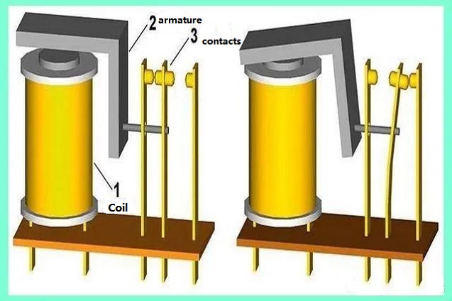
Fig. 1 Structure composition of relay
二、Basic parameters of relay
When choosing a relay, it is very important to know its basic characteristics. These characteristics include coil voltage, contact capacity, contact resistance, release voltage and so on.
When the relay works normally, the coil voltage is the voltage applied across the coil. When you buy a relay, you often ask, "How many volts of relay do you want?" .
The term "contact capacity" describes the relay's ability to handle loads, such as 2A/30VDC or 20A/220VAC;
When the voltage across the coil decreases, the voltage at which the contact is reset is called the release voltage.
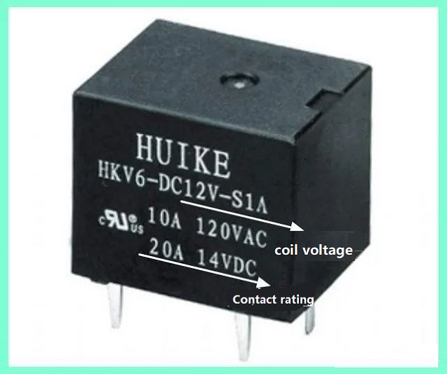
Figure 2 Physical diagram of relay
Relay connections of normally open, normally closed and normally open/normally closed combinations are common.
Ⅲ. Operation method of relay
Relay is basically the standard on the development board of single chip microcomputer, and all the friends who have studied single chip microcomputer know it. By controlling the relay, you can learn how to set the IO port of single chip microcomputer as output. Transistors can be used to drive low-power relays. The following is the circuit diagram of relay driven by NPN and PNP transistors.
NPN transistor driven relay
When using NPN transistor to operate relay, it is necessary to connect a reverse diode in parallel on the collector of relay, which is connected in parallel with the coil. Figure 3 shows the standard schematic diagram.
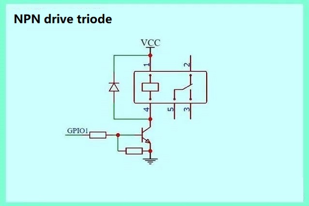
Fig. 3 NPN transistor driven relay
In the above figure, the pull-down resistor between the base and emitter and the current-limiting resistor on the base are used to prevent the base current from damaging the triode. When the IO port of single chip microcomputer is initialized for the first time, the level may be zero. The pull-down resistor disables the transistor under unknown conditions by pulling the base low to prevent the relay from failing.
When the base signal is at a high level, the triode is turned on, the relay coil is energized, and the relay contacts are attracted;
When the base signal is low, the triode is turned off, the relay coil loses power and the relay contact is reset;
PNP transistor driven relay
When using PNP triode to drive relay, it is necessary to terminate the collector of triode in the relay coil and connect a reverse diode in parallel on the coil. The typical schematic diagram is shown in Figure 4.
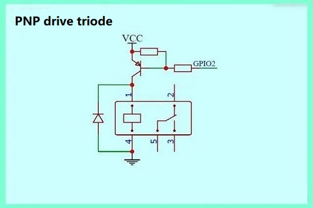
Fig. 4 PNP transistor driven relay
In the above figure, the pull-down resistor between the base and emitter and the current-limiting resistor on the base are used to prevent the base current from damaging the triode. When the IO port of single chip microcomputer is initialized for the first time, the level may be zero. The pull-down resistor disables the transistor under unknown conditions by pulling the base low to prevent the relay from failing.
When the base signal is at a high level, the triode is turned on, the relay coil is energized, and the relay contacts are attracted;
When the base signal is low, the triode is turned off, the relay coil loses power and the relay contact is reset;
The role of free-wheeling diode
In the first two driving modes, a freewheeling diode is connected in parallel above the coil. Because of the inductance characteristic, the relay coil will induce a reverse electromotive force, and the current flowing through the coil will not change suddenly when the power is cut off. If the reverse voltage exceeds the withstand voltage of the transistor, the transistor will be damaged, which should be avoided. In order to protect the triode when the power is cut off, a reverse freewheeling diode is added to provide a discharge channel for the reverse electromotive force.
四、How to save energy for relay
Nowadays, users are very concerned about power consumption and want to reduce power consumption as much as possible without sacrificing performance. This is very obvious for relays. Because of the extremely low coil resistance, some relays need a lot of current to start and run. The relay needs a large current to activate, but it only needs a small amount of holding current to keep the action state after activation. Therefore, in order to realize the energy saving of relay driver, the current flowing through the coil

Fig. 5 relay energy saving
There are two technologies that can save energy:
Save energy by descending.
When the relay is turned on, the rated voltage is applied across the coil. After the relay operates stably, the voltage at both ends of the coil drops above the release voltage for 100 to 500 milliseconds. In this way, a small voltage will be applied across the coil, and the current flowing through the coil will be very small. This is illustrated on the left side of Figure 5.
PWM technology energy saving
At present, the most popular energy-saving technology is to use PWM to drive the control terminal of triode or MOS tube to reduce the average voltage at both ends of the coil, so as to achieve the effect of energy-saving of the coil.
Fig. 6 depicts rough waveforms of the above two modes.
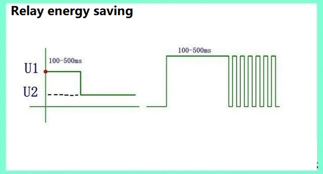
Fig. 6 relay energy saving
Ⅴ.Basic knowledge of solid state relay
The contact of electromagnetic relay is mechanical, and it is easy to be broken by high current, resulting in arc. If it works in arc environment for a long time, the contact will corrode and fail, so the contact of electromagnetic relay has a service life. Solid-state relay is an all-electronic relay, the contacts are realized by MOS tubes or thyristors, and there is no arc problem in electronic connection, so the contact life of solid-state relay is infinitely long, the response speed is fast, the noise is low, and there is no jitter problem.
Basic components of solid-state relay
Solid-state relays can be divided into AC solid-state relays and DC solid-state relays. The main components of AC solid-state relays are optocouplers and thyristors, while the main components of DC solid-state relays are optocouplers and MOSFET.
Zero-crossing detection of solid state relay
Solid-state relay has two types: zero-crossing detection and zero-crossing detection. For AC load without zero-crossing detection, if the input terminal has a trigger signal, the contact will act immediately. For load terminal with zero-crossing detection, if the input terminal has a trigger signal, the contact will not act until the load terminal has zero-crossing detection.
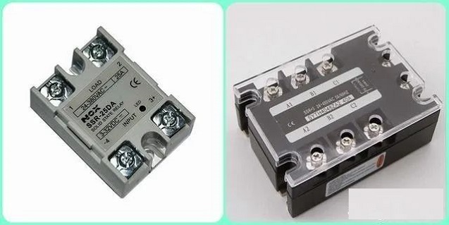
Fig. 7 Solid State Relay
Solid-state relay has electronic contacts. When the current is too large, it needs a large area radiator, which is more expensive than electromagnetic relay.
Both solid-state relay and electromagnetic relay have advantages and disadvantages.
